Categorías
Nuevo blog
¿Qué causa el bombeo en sopladores centrífugos pequeños y cómo pueden los ingenieros prevenir el flujo de aire inestable?
August 31 , 2026Los sopladores centrífugos pequeños se utilizan ampliamente en equipos electrónicos, dispositivos médicos, electrodomésticos, sistemas de refrigeración, equipos de baterías, equipos de carga, armarios de control, sistemas de ventilación y otras aplicaciones compactas. Dado que estos sopladores suelen instalarse en espacios reducidos, los ingenieros a menudo deben equilibrar el caudal de aire, la presión estática, el ruido, el consumo de energía, las dimensiones y la fiabilidad.
En muchas aplicaciones, seleccionar un soplador pequeño parece sencillo. Un ingeniero puede comparar el caudal de aire requerido con el caudal máximo indicado en la ficha técnica del producto y elegir un modelo con la capacidad suficiente. Sin embargo, el rendimiento real del caudal de aire puede variar considerablemente una vez instalado el soplador en un sistema de equipo completo.
La razón es sencilla: un soplador no funciona de forma independiente.
El ventilador debe superar la resistencia que generan los conductos de aire, filtros, disipadores de calor, rejillas de ventilación, codos, pasajes estrechos, intercambiadores de calor y otros componentes. Cuando esta resistencia es excesiva, el punto de funcionamiento del ventilador se desvía de su rango óptimo. El flujo de aire puede disminuir significativamente, la presión puede fluctuar y pueden aparecer ruidos o vibraciones inusuales.
En determinadas condiciones, la interacción entre el ventilador y el sistema de flujo de aire conectado puede producir una condición de funcionamiento inestable que se describe comúnmente como sobrepresión del ventilador o inestabilidad del flujo.
En las grandes máquinas centrífugas industriales, el fenómeno de sobretensión puede ser un problema aerodinámico grave que implica fuertes oscilaciones de presión y flujo. En el caso de los pequeños sopladores centrífugos utilizados en equipos compactos, la situación suele ser menos crítica. Es más probable que los ingenieros se encuentren con una alta resistencia del sistema, una reducción significativa del flujo de aire, fluctuaciones de presión, ruido pulsante o flujo de aire inestable antes de experimentar el comportamiento de sobretensión severo asociado con los grandes sistemas industriales.
Comprender esta distinción es importante al diseñar equipos con sopladores pequeños.
Este artículo explica qué significa el fenómeno de sobretensión en el soplador en el contexto de pequeños sopladores centrífugos, por qué una resistencia excesiva del sistema puede causar un flujo de aire inestable, cómo los ingenieros pueden identificar problemas potenciales y cómo una selección adecuada del soplador y un diseño apropiado del recorrido del flujo de aire pueden reducir el riesgo.
¿Qué es el sobrecalentamiento del soplador?
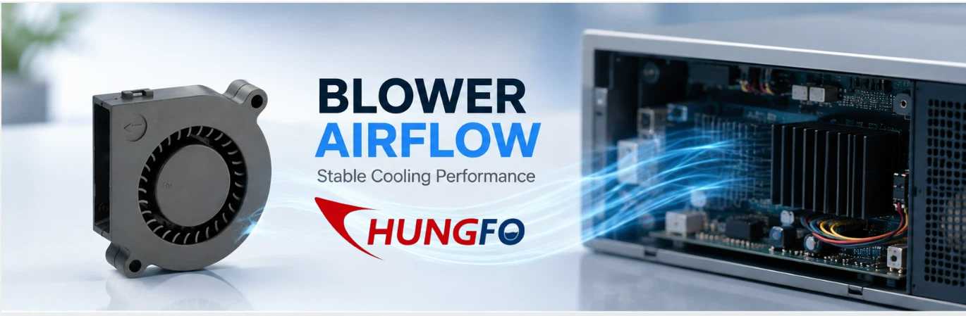
El fenómeno de sobrepresión en el soplador se refiere a una condición aerodinámica inestable en la que el flujo de aire y la presión generados por el soplador fluctúan en lugar de permanecer relativamente estables.
Este fenómeno está estrechamente relacionado con la relación entre el rendimiento del ventilador y la resistencia del sistema.
Cada soplador centrífugo tiene una curva de rendimiento. Esta curva normalmente muestra cómo varía el flujo de aire en función de la presión estática. Con baja resistencia del sistema, el soplador suele proporcionar un flujo de aire relativamente alto. A medida que aumenta la resistencia del sistema, el flujo de aire disminuye, mientras que el soplador opera a mayor presión.
Un sistema de equipos completo también tiene sus propias características de resistencia.
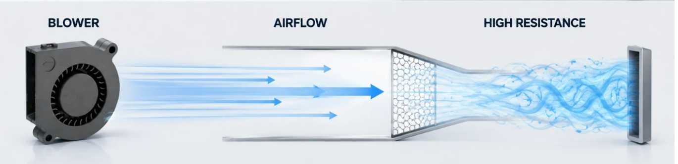
Por ejemplo, imaginemos un pequeño ventilador instalado dentro de un dispositivo electrónico. El aire entra por una rejilla de entrada, pasa por el ventilador, recorre un estrecho conducto interno, atraviesa un disipador de calor y sale por una pequeña abertura de ventilación.
Cada parte crea resistencia.
Si el conducto de aire está relativamente abierto, el ventilador puede funcionar en un punto estable con un flujo de aire razonable.
Si la salida se restringe, la resistencia del sistema aumenta.
Si un filtro se ensucia, la resistencia vuelve a aumentar.
Si el disipador de calor se contamina con polvo, la resistencia puede aumentar aún más.
Con el tiempo, el ventilador puede verse forzado a operar en una parte de su rango de funcionamiento donde el flujo de aire se vuelve muy bajo y el comportamiento aerodinámico se vuelve menos estable.
Dependiendo del diseño del ventilador y la configuración del sistema, esto puede provocar pulsaciones en el flujo de aire, fluctuaciones de presión, variaciones de ruido, vibraciones u otros comportamientos inestables.
Por lo tanto, los ingenieros no deberían considerar que las fluctuaciones del ventilador sean simplemente un problema interno del motor del ventilador.
Suele ser el resultado de la interacción entre el ventilador y todo el sistema de flujo de aire.
¿Es común que el ventilador presente fluctuaciones de velocidad en sopladores pequeños?
Esta es una pregunta importante para los diseñadores de equipos.
Los sopladores centrífugos pequeños pueden experimentar inestabilidad aerodinámica, pero los ingenieros deben tener cuidado al aplicar el término "sobretensión" a aplicaciones de sopladores compactos.
Los compresores centrífugos industriales de gran tamaño y los sopladores de proceso de gran tamaño pueden experimentar fuertes sobretensiones que implican una inversión sustancial del flujo y oscilaciones de presión. Los sopladores de CC pequeños utilizados para la refrigeración de componentes electrónicos o electrodomésticos generalmente operan a caudales mucho menores y volúmenes de sistema más pequeños.
Como resultado, los síntomas suelen ser diferentes.
Un soplador pequeño puede experimentar:
Flujo de aire reducido
Mayor presión estática
Flujo de aire pulsante
Cambio del ruido aerodinámico
Aumento de la vibración
Carga del motor fluctuante
Rendimiento de refrigeración reducido
Estas condiciones pueden deberse a una resistencia excesiva del sistema, incluso cuando no representan una sobretensión severa en el sentido industrial clásico.
Por lo tanto, para la comunicación en materia de marketing e ingeniería, es más preciso explicar que los sopladores centrífugos pequeños pueden experimentar un flujo de aire inestable o un comportamiento similar a una sobretensión en condiciones desfavorables del sistema.
Esta distinción otorga mayor credibilidad al debate técnico.
También ayuda a los clientes a comprender que elegir un soplador no se trata simplemente de encontrar un producto con el mayor caudal de aire.
Por qué la resistencia del sistema es tan importante
La resistencia del sistema es uno de los factores más importantes que afectan al rendimiento real de un pequeño soplador centrífugo.
Las especificaciones de un ventilador pueden indicar un valor máximo de flujo de aire. Sin embargo, el flujo de aire máximo generalmente se mide bajo condiciones de prueba específicas y puede ocurrir cuando el ventilador encuentra muy poca resistencia.
El equipo real es diferente.
Una vez instalado el ventilador, el aire debe circular por todo el recorrido del flujo de aire.
Un filtro crea resistencia.
Una rejilla crea resistencia.
Un disipador de calor crea resistencia.
Un conducto estrecho crea resistencia.
Un conducto largo crea resistencia.
Una curva pronunciada crea resistencia.
Un enchufe pequeño crea resistencia.
El efecto combinado puede ser significativo.
Por este motivo, los ingenieros deberían analizar la relación entre el flujo de aire y la presión estática, en lugar de considerar únicamente el flujo de aire máximo.
Por ejemplo, un ventilador que se anuncia con un alto caudal de aire libre puede proporcionar un caudal de aire considerablemente menor cuando se conecta a una estructura de refrigeración densa.
Esto es especialmente importante en equipos compactos, ya que los diseñadores suelen tener un espacio limitado para los conductos de aire.
Cuando el recorrido del flujo de aire disponible se reduce, la caída de presión puede aumentar rápidamente.
Si la resistencia del sistema se vuelve demasiado alta, el ventilador puede pasar la mayor parte del tiempo de funcionamiento en un punto de bajo caudal de aire y alta presión.
Esto puede reducir el rendimiento de la refrigeración y generar un comportamiento aerodinámico inestable.
La diferencia entre el flujo de aire libre y el flujo operativo real
Uno de los errores más comunes al seleccionar un ventilador es comparar únicamente los valores de flujo de aire libre.
El flujo de aire libre describe una condición con mínima resistencia externa.
Los equipos reales casi nunca funcionan en condiciones totalmente ilimitadas.
Consideremos una aplicación de refrigeración en la que se utiliza un ventilador para forzar el paso del aire a través de un disipador de calor.
Si el disipador de calor tiene aletas muy juntas, la resistencia al flujo de aire puede ser significativa.
Ahora añade un filtro de polvo.
Luego, agregue una salida estrecha.
Luego, añade dos curvas en el conducto de aire.
La resistencia final del sistema puede ser mucho mayor que la sugerida en el cálculo original.
El soplador debe superar todas estas pérdidas de presión.
En consecuencia, el flujo de aire real puede ser mucho menor que el valor mostrado en condiciones de aire libre.
Por eso, al seleccionar un soplador profesional, siempre se debe tener en cuenta la presión prevista del sistema.
¿Qué causa la inestabilidad del flujo de aire en los pequeños sopladores centrífugos?
Diversos factores pueden contribuir a la inestabilidad del flujo de aire.
La primera es la restricción excesiva de salidas.
Si la abertura de salida es demasiado pequeña, el ventilador debe generar mayor presión para mover el aire a través del sistema.
El segundo es un conducto de aire de tamaño insuficiente.
Un paso estrecho aumenta la velocidad del aire y la pérdida de presión.
La tercera es una resistencia excesiva del filtro.
Los filtros se vuelven aún más restrictivos cuando se acumula polvo.
El cuarto es un diseño deficiente de la entrada de aire.
A blower needs a suitable air supply. If the inlet is partially blocked or airflow enters the impeller unevenly, aerodynamic performance may deteriorate.
The fifth is excessive duct bending.
Sharp bends close to the blower can create turbulence and uneven velocity distribution.
The sixth is improper blower selection.
A blower that is too small may not have sufficient pressure capability for the application.
A blower that is too large may create excessive pressure and force the system to use restrictive control methods.
The seventh is changing operating conditions.
A system may work well during initial testing but become less stable after filters become dirty or when equipment configuration changes.
Why Small Blower Size Does Not Mean Simple Airflow Design
Because small blowers occupy very little physical space, designers sometimes assume that airflow design is also simple.
In reality, compact systems can be more challenging.
A large industrial ventilation system may have sufficient space for smooth ducts, gradual transitions, large filters, and appropriately sized outlets.
A compact electronic device may have only a few centimeters of available space.
The designer may need to route air around circuit boards, heat sinks, batteries, cables, brackets, and structural components.
This creates many local restrictions.
A blower may have excellent performance when tested alone, but the same blower can perform very differently after installation.
Therefore, compact blower applications require careful attention to the complete airflow path.
How To Recognize Potential Blower Instability
Engineers and maintenance personnel can look for several warning signs.
The first is unusual airflow fluctuation.
If the equipment operates under a stable thermal load but airflow repeatedly changes, the airflow path should be inspected.
The second is pressure fluctuation.
A pressure sensor can help identify changes in system pressure that may not be obvious from airflow measurements alone.
The third is unusual noise.
A small blower operating normally should produce relatively consistent aerodynamic noise. Pulsating or changing noise can indicate turbulence, excessive restriction, or unstable airflow.
The fourth is increased vibration.
Aerodynamic instability can create changing forces on the impeller and housing.
The fifth is reduced cooling performance.
If electronic components become hotter even though blower speed has not changed, system resistance or airflow restriction may have increased.
The sixth is changing motor current.
Changes in aerodynamic loading can affect the electrical load of the motor.
These symptoms should be evaluated together rather than individually.
Does Higher RPM Always Solve The Problem?
Increasing blower speed can increase airflow and pressure, but it should not automatically be treated as the solution.
Suppose a filter is becoming blocked.
The equipment begins to experience reduced airflow.
An operator increases blower speed.
Airflow improves temporarily.
However, the filter remains blocked.
The blower now operates at a higher speed and may consume more power while generating higher pressure.
If the system resistance continues increasing, the operating condition may eventually become unfavorable again.
Therefore, higher speed can compensate for some operating changes, but it cannot replace proper airflow-path design and maintenance.
Engineers should always determine why airflow is declining before simply increasing speed.
Selecting The Right Blower Performance
For small centrifugal blowers, the most important selection information includes airflow, static pressure, operating voltage, speed, noise, dimensions, power consumption, operating temperature, and expected service life.
Among these parameters, the airflow-pressure relationship is particularly important.
The required operating point should be identified first.
For example, if the equipment requires a certain airflow while overcoming a defined static pressure, the selected blower should be able to provide that combination under the actual operating conditions.
This is much more meaningful than selecting a blower simply because its maximum airflow is higher than the required value.
Engineers should also consider the operating range.
If the equipment can experience changes in filter condition, temperature, valve position, or airflow demand, the blower should maintain acceptable performance across those conditions.
40mm Blower FanApplications And Airflow Stability
A 40mm blower fan is typically associated with compact equipment where installation space is limited.
Such small blowers can be useful for localized cooling inside electronic devices, control systems, instruments, communication equipment, and other compact assemblies.
However, their small size means that the airflow path can have a relatively large influence on total system resistance.
A small outlet that appears acceptable visually may represent a significant restriction relative to the blower's available airflow area.
Likewise, a narrow internal channel may consume a large portion of the available pressure.
Therefore, when designing a system around a 40mm blower fan, engineers should evaluate the complete airflow path rather than only the blower itself.
The inlet area, outlet area, duct length, bends, filters, and heat dissipation components should all be considered.
100mm Blower FanApplications
A 100mm blower fan provides more installation flexibility than extremely compact blowers in some applications and may be selected when greater airflow or pressure capability is required.
However, larger physical size does not automatically eliminate airflow instability.
A 100mm blower fan can still operate under excessive system resistance if the connected duct, filter, heat exchanger, or outlet is improperly designed.
The same selection principle therefore applies.
Engineers should match the blower to the actual system operating point.
The objective is stable airflow rather than simply maximum airflow.
Blower 5015And Compact Cooling Design
A blower 5015 is an example of the type of compact blower format that can be considered for space-constrained cooling applications.
When using compact blowers of this type, designers should pay particular attention to the relationship between blower dimensions and airflow-path dimensions.
A compact blower may fit easily into the equipment, but the surrounding structure can still restrict airflow.
For example, placing the blower directly against a narrow wall or mounting bracket may reduce the effective inlet area.
Similarly, connecting the outlet to a narrow passage may increase pressure loss.
These details can influence actual performance more than the nominal blower dimensions suggest.
How Inlet Design Affects Blower Performance
The blower inlet is often overlooked.
Air should be able to enter the blower smoothly and reasonably uniformly.
If the inlet opening is partially blocked, the blower may have to operate with an uneven velocity distribution.
A sharp bend immediately before the inlet can also create turbulence.
In compact equipment, engineers may need to position the blower close to other components because of space limitations.
However, leaving adequate inlet clearance can improve airflow quality.
The inlet grille should also provide sufficient open area.
A decorative grille may look attractive but create unnecessary pressure loss if its open area is too small.
How Outlet Design Affects System Resistance
The outlet is equally important.
A blower may generate sufficient pressure, but if the outlet cannot pass the required airflow, system resistance will increase.
The outlet should be appropriately sized.
Sudden contractions should be avoided where possible.
Sharp changes in direction should be minimized.
If a protective grille is required, its open area should be evaluated.
If a filter is installed at the outlet, its pressure drop should be included in the system calculation.
These small design decisions can have a significant effect on the final operating point.
Filters And Their Impact On Blower Operation
Filters are important for protecting equipment from dust, but they inevitably create pressure loss.
A new filter may have relatively low resistance.
After extended operation, dust accumulation can increase pressure drop.
This means the blower operating point can gradually change over time.
A cooling system that performed well during initial testing may therefore deliver less airflow several months later.
For equipment requiring stable thermal performance, filter condition should be included in the maintenance plan.
Engineers should also specify the acceptable filter pressure drop rather than treating filtration as an isolated component.
Heat Sinks Can Also Create Significant Resistance
Heat sinks are widely used in electronic cooling systems.
While a heat sink improves heat transfer, closely spaced fins can restrict airflow.
If the blower must force air through a dense fin structure, static pressure requirements increase.
The thermal engineer should therefore consider both heat transfer and pressure loss.
A heat sink with extremely dense fins may provide a large heat transfer surface but require more blower pressure.
A slightly different fin spacing may reduce pressure loss while still providing adequate thermal performance.
The best solution is usually a balance between thermal performance and airflow resistance.
The Importance Of System Testing
Calculations are important, but prototype testing is often necessary.
A small blower should ideally be tested inside the actual or representative equipment.
Testing should measure airflow, pressure, temperature, noise, vibration, and motor electrical parameters where appropriate.
The equipment should be tested under different thermal loads.
Minimum, normal, and maximum operating conditions should be evaluated.
If the system uses a filter, test both clean and representative loaded conditions when practical.
If the blower uses speed control, the complete control range should also be tested.
This approach allows engineers to identify problems before mass production.
How Engineers Can Reduce Surge Risk
The first step is to reduce unnecessary system resistance.
Use appropriately sized airflow channels.
Avoid unnecessary bends.
Provide adequate inlet and outlet areas.
Select filters with suitable pressure-drop characteristics.
Avoid excessive restrictions around heat sinks.
Choose the blower based on the actual airflow-pressure requirement.
Provide sufficient operating margin.
Use appropriate speed control when necessary.
Monitor system performance during operation.
Maintain filters and airflow paths.
These measures can significantly improve airflow stability.
Should Engineers Choose A Higher Pressure Blower?
Sometimes a higher pressure blower is appropriate.
If the system contains dense heat sinks, long ducts, filters, or other restrictive components, the blower needs enough pressure capability to maintain the required airflow.
However, selecting the highest pressure blower available is not always the best solution.
The blower should be matched to the system.
Too little pressure capability results in insufficient airflow.
Excessive pressure capability may increase noise, power consumption, and the need for restrictive control.
The correct solution is the blower that can provide the required airflow at the required static pressure while operating within a suitable region of its performance curve.
How Speed Control Can Help
Speed control can help compensate for changes in cooling demand.
When thermal load increases, blower speed can be increased within the permitted operating range.
When thermal load decreases, speed can be reduced.
This can improve energy efficiency and reduce unnecessary noise.
However, the control system should have defined operating limits.
It should not continuously command the blower into an unstable region.
For critical equipment, pressure or airflow feedback can be used to improve control accuracy.
The Role Of Motor And Impeller Design
Although system resistance is extremely important, blower construction also influences stability.
Impeller geometry determines how air is accelerated and pressurized.
Housing geometry affects the airflow path.
Motor speed affects pressure and airflow capability.
Impeller balance affects vibration.
Bearing quality influences mechanical reliability.
Material selection affects temperature resistance and structural stability.
Therefore, engineers should consider both aerodynamic performance and mechanical design when evaluating a blower.
Why Noise Can Be An Early Warning Sign
Noise is often one of the first things that users notice.
A change in sound may indicate increased turbulence or unstable airflow.
For compact equipment, noise is particularly important because users may be close to the product.
If a blower becomes noticeably louder after installation, engineers should check whether the airflow path is causing excessive pressure loss.
The noise may not be caused by the blower itself.
A narrow outlet, grille, duct bend, or turbulent transition can create significant additional aerodynamic noise.
Why Vibration Should Not Be Ignored
Vibration in a small blower can have several causes.
Mechanical imbalance is one possibility.
Bearing problems are another.
Improper mounting can also increase vibration.
However, aerodynamic instability should also be considered.
If vibration increases together with airflow fluctuation and changing noise, the system should be evaluated as a whole.
Replacing the blower without correcting the airflow restriction may not solve the problem.
Designing For Long-Term Reliability
A blower that performs well on the first day should continue performing well months or years later.
Long-term reliability requires consideration of dust accumulation, temperature, filter loading, component aging, changing operating conditions, and maintenance access.
The airflow system should therefore be designed with maintenance in mind.
Filters should be accessible.
Air channels should not be unnecessarily narrow.
Critical components should not be placed directly in front of the inlet.
Cleaning should be practical.
Sensors should be positioned where they can provide useful information.
These design details can significantly improve the long-term stability of the cooling system.
A Practical Troubleshooting Process
When a small blower system begins showing unstable airflow, engineers can follow a structured troubleshooting process.
First, confirm whether the required airflow and thermal load have changed.
Second, inspect the inlet.
Third, inspect the outlet.
Fourth, check filters and grilles.
Fifth, inspect heat sinks and ducts.
Sixth, measure static pressure.
Seventh, measure actual airflow.
Eighth, compare the measured operating point with the blower performance curve.
Ninth, check motor speed and electrical current.
Tenth, inspect mounting, vibration, and mechanical condition.
This process is more reliable than immediately replacing the blower.
Working With A Professional Blower Manufacturer
For equipment manufacturers, early communication with the blower supplier can simplify product development.
Instead of providing only the desired blower dimensions, engineers should provide the actual application requirements.
Useful information includes required airflow, estimated static pressure, operating voltage, available installation space, operating temperature, noise requirements, expected operating hours, and environmental conditions.
The blower manufacturer can then recommend a suitable performance range.
For customized applications, prototype testing can further improve confidence.
This approach can help prevent the common problem of selecting a blower according to dimensions first and discovering later that the actual airflow is insufficient.
China Chungfo Fan And Small Blower Applications
Chungfo Fanfocuses on the development and production of cooling fans, centrifugal blowers, axial fans, cross-flow fans, and other air-moving products for different equipment applications.
For compact blower applications, the selection process should begin with the complete airflow requirement rather than a single dimensional parameter.
Airflow, static pressure, voltage, speed, noise, operating temperature, installation conditions, and expected service life all need to be considered.
This application-oriented approach is especially important when a small blower is installed in a compact enclosure.
The blower itself may occupy only a small area, but the surrounding airflow structure can strongly influence its actual performance.
By evaluating the complete system, engineers can better balance cooling performance, energy consumption, noise, installation space, and reliability.
Final Thoughts
Small centrifugal blowers are highly useful for compact cooling and ventilation applications, but their performance depends strongly on the system in which they are installed.
Blower surging in the classical industrial sense is not necessarily the most common problem for small electronic or appliance blowers. However, unstable airflow, high system resistance, pressure fluctuation, pulsating noise, vibration, and significant airflow reduction are all important issues that engineers should understand.
The key lesson is that maximum airflow is not enough for blower selection.
The real operating point depends on both the blower and the system.
A small blower connected to a restrictive airflow path may deliver much less airflow than expected. Increasing speed may temporarily compensate for the problem, but it does not eliminate the underlying resistance.
Engineers should therefore evaluate the complete airflow path, including the inlet, outlet, filters, ducts, heat sinks, grilles, bends, and other components.
The blower should be selected according to the required airflow and static pressure, and the system should be validated under realistic operating conditions.
For compact applications using products such as a 40mm blower fan, a 100mm blower fan, or a blower 5015, careful system design is particularly important because limited installation space can create significant airflow restrictions.
Ultimately, stable blower operation comes from matching the blower to the real system rather than simply selecting the largest airflow specification.
When blower selection, airflow-path design, testing, control, and maintenance are considered together, engineers can achieve more reliable cooling performance, lower unnecessary noise, better energy efficiency, and longer equipment life.
FAQ
What is blower surging?
Blower surging is an unstable airflow condition in which pressure and airflow fluctuate instead of remaining relatively stable. In small blower applications, engineers may more commonly encounter airflow instability caused by excessive system resistance.
Can a small centrifugal blower experience surge?
Yes, small centrifugal blowers can experience aerodynamic instability under unfavorable operating conditions. However, the behavior is often less severe than the classical surge phenomenon associated with large industrial centrifugal machines.
What usually causes unstable airflow in a small blower system?
Common causes include excessive outlet restriction, narrow ducts, dirty filters, dense heat sinks, poor inlet design, sharp bends, improper blower selection, and changing operating conditions.
Does a higher RPM always solve low airflow?
No. Increasing speed can increase airflow and pressure, but it cannot remove a blocked filter, undersized duct, or restricted outlet. The underlying system resistance should be investigated first.
Why is static pressure important for small blower selection?
Static pressure indicates how much resistance the blower must overcome. A blower with a high free-air airflow rating may provide much less actual airflow when connected to a restrictive system.
Can a 40mm blower fan be used for high-resistance applications?
It can be used when its performance curve provides sufficient airflow at the required static pressure. The compact size alone does not determine whether it is suitable.
Is a 100mm blower fan automatically more stable?
Not necessarily. A larger blower may provide greater airflow or pressure capability, but stability still depends on the relationship between the blower and the connected airflow system.
What should engineers check when blower noise suddenly increases?
They should inspect the inlet, outlet, filters, ducts, grilles, heat sinks, mounting structure, and operating point. Increased noise may result from turbulence or excessive system resistance rather than a defective blower.
Can a blower 5015 be used in compact electronic equipment?
Compact blower formats can be suitable for electronic equipment when their airflow and pressure characteristics match the application's requirements. Engineers should evaluate the complete airflow path before final selection.
How can engineers reduce the risk of unstable airflow?
Engineers can reduce unnecessary system resistance, provide adequate inlet and outlet areas, select suitable filters, design smoother airflow paths, choose the blower according to the required airflow and static pressure, and validate the system under realistic operating conditions.
Should a blower always be selected with the highest possible airflow?
No. Maximum airflow is only one parameter. The blower should provide the required airflow at the actual system static pressure while operating within an appropriate and stable range.
Can dirty filters affect blower performance?
Sí. La acumulación de polvo aumenta la resistencia del filtro, lo que puede reducir el flujo de aire y modificar el punto de funcionamiento del ventilador. La inspección y el reemplazo periódicos son importantes para mantener un rendimiento estable.
¿Por qué se debe probar el rendimiento del ventilador después de la instalación?
Esto se debe a que el equipo real genera una resistencia que puede no existir durante las pruebas al aire libre. Las condiciones de instalación pueden modificar significativamente el flujo de aire, la presión, el ruido, la temperatura y el consumo de energía.
¿Qué información deben proporcionar los ingenieros al solicitar una recomendación sobre un soplador?
La información importante incluye el caudal de aire requerido, la presión estática, la tensión de funcionamiento, las dimensiones de instalación, la temperatura de funcionamiento, los requisitos de ruido, el ciclo de trabajo, las condiciones ambientales y la vida útil prevista.
¿Cuál es el principio más importante a la hora de seleccionar un soplador centrífugo pequeño?
El principio más importante es adaptar el caudal de aire y el rendimiento de presión del soplador al punto de funcionamiento real del sistema, en lugar de seleccionar un producto basándose únicamente en su tamaño físico o caudal de aire máximo.